Click the pencil icon at right to make changes or configure each logic parameter:
Logic Inputs and Output settings allow users to configure actions in both the Qt X platform and with connected 3rd party devices. The two primary purposes of the Logic IO are as follows:
Trigger an action as an 'input' within the Qt X platform
Trigger a 3rd party external device as an 'output' from the Qt X platform
The following settings are available in the Web UI within the Logic user interface for all Qt X control processors:
Contact Inputs (Push to Talk & Emergency Mute)
Privacy Sign Outputs
Two Assignable GPIO Contacts
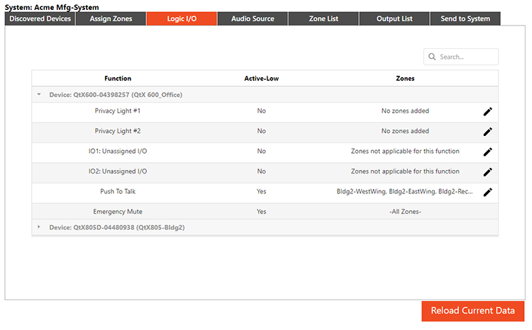
If devices have been configured previously, zones and Active-Low status will be shown:
Click the pencil icon at right to make changes or configure each logic parameter:
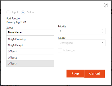
Privacy 1 & 2 (light panels that indicate the status of sound masking,) do not have any audio functions nor priority (nothing will override the Privacy Light function.) Privacy Lights may only be set to activate or not. The following parameters dictate when the privacy lights will activate in the selected zone:
Sound Masking must be enabled
Sound Masking is not set to mute
Sound Masking is set to higher than -20dB
GPIO (IO1 & IO2) allow a user to select appropriate audio devices assigned in the Audio Sources tab. 'Unassigned I/O' will select by default.
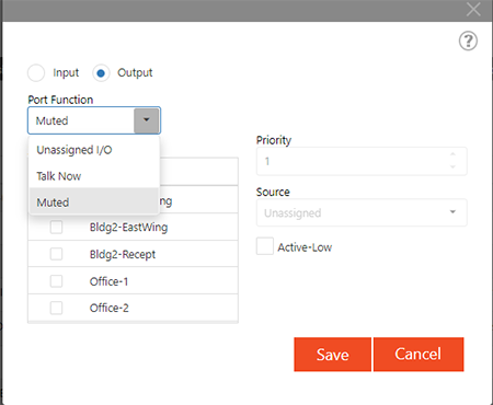
Users have the option to select Mute and Talk Now from the drop-down if left assigned as an Output (Input not selected)
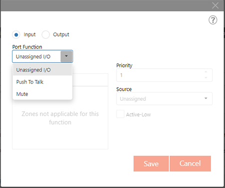
If selected as an Input, the drop-down selections change to Mute and Push to Talk.
Selecting Active Low is always available on the GPIO ports.
Priority may be changed and a single or multiple zones may be selected.
Selecting Mute will disallow selection of an Audio Source, as this functionality mutes all audio in the selected zones.
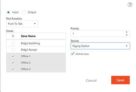
Push to Talk is a paging microphone function and is set automatically as an input (not editable).
Users may select the audio source type from the drop down (assigned in the tab).
Priority may be changed and a single or multiple zones may be selected.
Emergency Mute is a dry contact closure and select-able in a high or low state. A Fire contact will propagate to all controllers in a system when activated from this port.
When assigning functions for GPIO IO1 and IO2, users will be given different options depending on whether Input or Output is initially selected, if the zone is applicable to the function selected and if an appropriate audio device is selected. More information on Logic function and basic use cases is available at the bottom of this section.
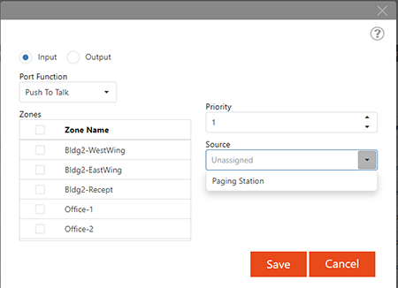
When available to edit, Input and Output Port Functions may be set as shown below.
Input Port Functions:
Output Port Functions:
Additional configurations such as Priority and Source may be selected depending on the Port Function selection.
Priority determines if a page will preempt a page that is in progress. The lower the number, the higher the priority. Therefore a paging source set to Priority 1 will override any page set to Priority 2.
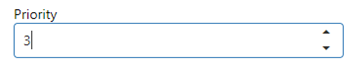
The priority field can only be edited for GPIO IO1 or IO2 when Push To Talk is selected. It can also be edited for the dedicated Push To Talk.
Source allows the user to select the audio source from the drop-down. Audio sources may be added and edited with the Audio Source tab. Only sources applicable to the port function will show as choices.
The section that follows gives information about the physical connections, behavior and high-level use-cases for logic. Detailed information around physical connections is given in the Qt X Installation & Operation Guide.
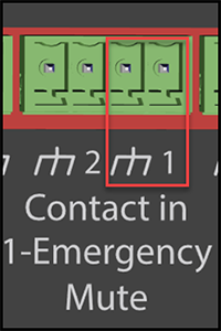
When an incoming signal is closed (Active Low) all sound masking zones, background music sources and paging will be muted. This mode activates when wires are connected at Pin 1 and Ground (  ).
).
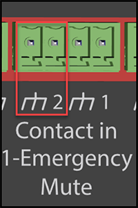
When an incoming contact is closed (Active Low) the audio source shown will be sent to all zones selected in the Zone drop-down. This results in muting of any background music in the selected zones. Paging will occur in the same zones at the level selected from the zones tab (paging).
A bus toggles between the background music and the paging. In order to hear/adjust paging levels the contact must be closed (a connected paging mic live) and adjustments made to the paging level in the appropriate zone.
Note that Push to Talk behavior on contact two is identical to the GPIO Push to Talk described below, but Active Low is the only option.
Two 5 VDC outputs are available to connect light panels that will indicate sound masking is active in a specific zone.
Both Privacy 1 and Privacy 2 are connected and operate as follows:
Connect the positive lead of a privacy sign to Pin 1 and Ground ( ) and/or Pin 2 and Ground ( ) if installing two signs while observing polarity. Select the Zone (one zone per output) from the software to associate to the privacy light indication. When sound masking is active in the associated zone (above -20dB) the associated privacy light will illuminate. The Active-Low option isn't necessary and is disabled.
Two GPIO contacts may be configured as an input or output trigger in either an 'Active Low' or 'Active High' state. This allows 'events' to be triggered to offer functionality within the the Qt X (as an input) or to indicate a condition within the Qt X (as an output). These functions are described below:
When connected and set to 'Active Low' in software, the zones selected will mute sound masking, background music and paging sources (muting all sound) upon a contact closure (when the circuit is closed).
In the state shown below all audio is muted to the selected zones when the circuit is closed:
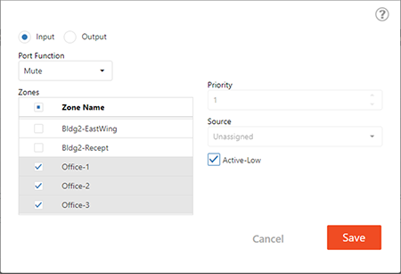
Although there are likely few, if any, practical uses cases, if set to 'Active High' in software ('Active Low' not checked,) all sources will mute when the contact is open.
IMPORTANT: Mute functionality should only be used in situations where it is permissible to disable a zone in very particular instances, such as a conference room with audio conferencing technology. Sound masking should never be muted in regularly-occupied areas.
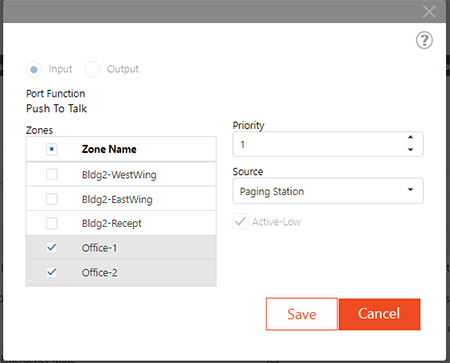
When connected and set to 'Active Low' in software, the audio source shown ('Paging Station' in the example) will be sent to all zones selected when the contact is closed. This mutes background music in the selected zones; the audio source chosen will play and is adjustable on the Zone Paging Level control.
Although 'Active Low' would be the most common use-case, 'Active High' may be applied as necessary. Changing the state to 'Active High' (Active Low not checked) will route the selected audio source to the selected zone(s) when the contact is open. A connected paging mic would be live at all times, so this use case may be limited to instances where a microphone receptacle is located in a space and is connected for a specific purpose/time (such as a lunch room or other space that may require amplified speech for meetings, etc.).
In the state shown below, when the circuit is closed, audio will stream to the selected zones:
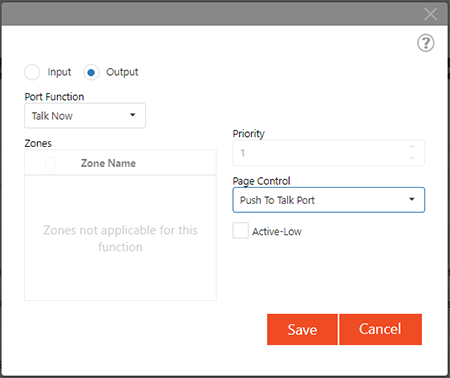
When selected as an output, this function will provide an indication of the state of the Push to Talk (contact input #2) or any available IO port that has been configured as an Input - Push to Talk. The associated port is determined by the selected device listed in the Audio Source drop down. This functionality can indicate that a person may speak into a microphone by illuminating an LED (+5 VDC) when a specific push to talk contact is active.
Connect Pin 1 or 2 (depending on the IO output port) and Ground ( ). If software is in an 'Active High' state, the connected LED will illuminate when the associated push to talk input is active. Selecting 'Active Low' in software will provide +5 VDC to the Talk Now output port when the associated Push to Talk input is inactive, thus indicating a paging microphone standby condition.
Provides an indication of the GPIO Input Mute condition present in a specific zone. When in an 'Active High' state ('Active Low' unchecked,) a mute initiated by the GPIO input on any of the selected zone(s) will result in +5 VDC across Pin 1 or 2 (depending on the output port) and Ground ( ).
If the output is set to 'Active Low,' this will indicate the selected zone is not muted.
Although the practical use cases are limited, setting the Mute to Active Low will result in all zones muted unless the signal is closed.
IMPORTANT: Mute functionality should only be used in situations where it is permissible to disable a zone in very particular instances, such as a conference room with audio conferencing technology. Sound masking should never be muted in regularly-occupied areas.
